 Integrating a 6-14S 180A ESC: Power-Path, SBEC, Thermal, and Commissioning Method
An electronic speed controller is often selected by matching three headline numbers: battery cell count, continuous current, and peak current. That is necessary, but it is not an engineering integration. A high-voltage ESC sits at the intersection of the battery, wiring, connectors, motor, propeller or rotor, receiver, flight controller, servos, telemetry bus, cooling path, and fail-safe logic. A mismatch in any one of those interfaces can produce voltage collapse, overheated joints, receiver resets, unexpected motor response, or a protection event at the exact moment the propulsion system is most heavily loaded.
This article uses the
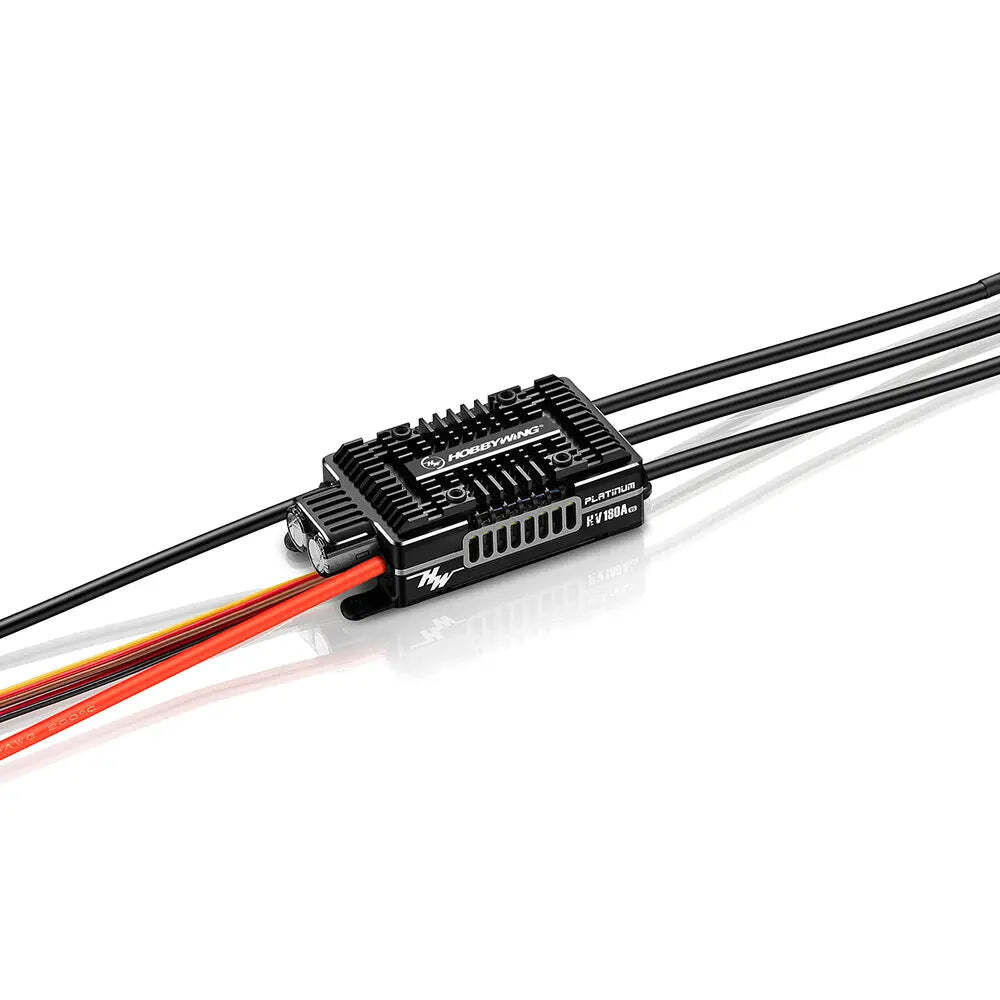
HOBBYWING Platinum HV 180A SBEC V5 listing at UNITED UAV as a concrete example. The manufacturer identifies it as product 30209103, specifies a 6–14S LiPo input, lists 180A continuous and 260A peak current, and provides a programmable 5–12V switch-mode BEC rated at 10A continuous and 30A peak. The stated application scope is 550–700-class electric helicopters or fixed-wing aircraft. Those statements define a component envelope; they do not prove that a particular motor, propeller, airframe, connector, installation, or mission is safe. The objective here is to turn the published envelope into a reviewable integration and acceptance process.
1. Convert labels into electrical boundary conditionsBegin with voltage at every relevant state, not the nominal pack label. A standard LiPo cell charged to 4.2V makes a 14S pack approximately 58.8V immediately after charging, while a 6S pack is approximately 25.2V. Confirm the actual battery chemistry, charger termination voltage, series count, and any high-voltage cell setting before connecting the ESC. A controller marked 14S must not be exposed to a pack whose fully charged voltage exceeds the manufacturer's limit. Also account for regenerative or commutation-related voltage excursions; the absence of an over-voltage event on a short bench run is not proof that the installed system will remain inside its limit during rapid unloading.
Current labels need an equally careful interpretation. At 58.8V, 180A represents about 10.6kW of electrical input at that instant; 260A represents about 15.3kW. These arithmetic products are not output-power ratings and are not promises of continuous operation at those levels. Motor efficiency, ESC switching loss, conductor loss, connector loss, cooling air, duty cycle, ambient temperature, timing, PWM strategy, and mechanical load all change the result. The peak rating is especially incomplete without its permitted duration and starting temperature. If the project needs a defined transient, obtain the manufacturer's current-versus-time condition rather than treating 260A as a general operating point.
Create a boundary table with maximum charged-pack voltage, expected steady current, worst credible transient current, transient duration, minimum in-flight voltage, ambient-temperature range, cooling condition, and maximum component temperature. Populate expected current from motor and propeller test data at the actual voltage. A static thrust stand can reveal a high-current point, but it may not reproduce the cooling or dynamic load of flight. A helicopter governor transient, a fixed-wing propeller unloading in the air, and a stalled motor are fundamentally different events. Keep the uncertainty visible instead of hiding it inside a single "maximum amps" cell.
2. Match the motor and mechanical load before tuning the ESCThe motor, gear ratio, rotor or propeller, and pack voltage determine what the ESC must switch. Verify motor Kv, winding configuration, pole count, insulation voltage, phase-current capability, allowable timing range, and manufacturer-recommended controller settings. On a fixed-wing aircraft, propeller diameter, pitch, blade count, air density, and inlet condition can shift current materially. On a helicopter, main-gear ratio, rotor speed, blade loading, governor target, and collective transients shape the load. A current prediction based on a different propeller or a partially discharged pack is not an acceptance test.
Do not use the ESC rating as a target. The desired operating region is one in which measured current, semiconductor temperature, capacitor temperature, wiring temperature, and voltage remain inside documented limits with margin. Select that margin for the consequences of failure and the quality of the test evidence. A commercial fixed-wing platform that depends on one propulsion channel may require a different margin and monitoring plan from a sport helicopter. If the intended aircraft is outside the manufacturer's published application scope—including a multirotor or another UAV architecture—request written compatibility guidance and validate the control mode, motor characteristics, cooling, and fail-safe behavior. The word "high-power" does not make one controller universally interchangeable across aircraft types.
3. Design the battery-to-ESC path as a complete circuitThe official specifications list one red and one black 10AWG input lead, each 255mm, and three black 10AWG motor leads, each 150mm. They also state that input and output connectors are not supplied. That makes connector selection, soldering, insulation, strain relief, and polarity control part of the integrator's responsibility. Select a connector using its documented continuous current, transient current, voltage, contact-temperature rise, mating-cycle life, retention, and environmental suitability. A connector advertised with a large ampere number but tested under unknown conditions is weak evidence for a flight-critical joint.
Keep the high-current loop compact without shortening or extending wires casually. Added battery-lead length increases inductance and can aggravate voltage overshoot at the ESC input. If installation geometry requires longer leads, obtain the controller manufacturer's guidance on added capacitance, capacitor placement, and maximum length. Do not move input capacitors away from the controller or substitute a capacitor solely by matching capacitance; voltage rating, ripple-current rating, equivalent series resistance, temperature, and mechanical support matter. Route positive and negative conductors together to reduce loop area, while maintaining clearance from receiver antennas, GNSS, magnetometers, and low-level sensor wiring.
Use a controlled soldering process. Strip only the required insulation length, prevent loose strands, fully wet the conductor and terminal, limit heat exposure to the controller, and support the joint while it cools. After assembly, inspect for incomplete wetting, solder spikes, heat-damaged insulation, exposed conductor, and a joint that can flex at the solder boundary. Apply strain relief to the cable, not to a fragile circuit-board termination. Verify polarity with a meter and a second-person check before connecting a battery. The
manufacturer's Platinum 180A HV SBEC V5 manual specifically warns that poor soldering can cause shorts or damage and instructs users to disconnect the battery after use.
4. Treat inrush and arcing as system behaviorLarge input capacitors initially appear close to a short circuit, so plugging in a high-voltage pack can produce substantial inrush current. The manufacturer describes a built-in anti-spark circuit, but this does not remove the need for connector inspection, correct connection order, or a defined arming procedure. Verify the behavior with the actual pack and connector. Repeated pitting, discoloration, softened housings, or increasing connection resistance indicates a problem even when the aircraft still arms normally.
Define an unambiguous safe state for maintenance: propulsion battery disconnected, stored energy allowed to discharge, and the motor treated as capable of starting until verified otherwise. Never use a propeller or rotor as a visual indicator that power is absent. If the airframe has a separate avionics or backup battery, document which systems remain energized after the propulsion pack is removed. Labels, accessible disconnects, and a checklist reduce the chance that a technician works on an apparently quiet but powered system.
5. Engineer the SBEC as an avionics power supplyThe built-in switch-mode BEC is specified as adjustable from 5V to 12V in 0.1V increments, with 10A continuous and 30A peak output. This is an interface specification, not permission to set 12V for every receiver, flight controller, servo, or accessory. Build a load inventory showing each device's allowed voltage, steady current, startup current, stall current, and transient behavior. The lowest maximum-voltage limit on the shared rail governs the setting. A single 8.4V-rated device on a nominal 12V bus can be destroyed even if the BEC itself is operating correctly.
Measure the rail at the actual loads. Exercise servos simultaneously, operate landing gear or payload actuators, transmit telemetry, and create the highest credible receiver/flight-controller demand while logging minimum bus voltage. Servo stall current can be far above its moving current, and multiple digital servos can align their peaks. A 30A peak statement is incomplete without duration, input voltage, airflow, and permitted voltage droop. Acceptance should therefore be based on recorded rail voltage, connector temperature, BEC temperature, and device behavior under a scripted load case.
If a backup receiver battery or redundant supply is planned, do not simply parallel sources. Check whether the architecture permits current sharing, reverse current, independent fault isolation, and safe charging states. The manufacturer describes an anti-reverse BEC circuit, but the complete redundancy design still depends on the second supply, wiring, switches, and power-distribution unit. Test loss and restoration of each source without a receiver reset or unexpected motor command. Record which source powers telemetry and the ESC control electronics when the propulsion pack is absent.
6. Make cooling measurableThe manufacturer's product page describes a double-sided heat sink, a side vent, and airflow intended to pass through the controller. Published size and weight—100.6 × 45.5 × 26.1mm and 250.6g—are stated without the fan. The programming interface can also be used to power a cooling fan. Confirm whether a fan is included in the purchased package and whether the intended installation requires it. A component photographed in open air can behave very differently inside a fuselage pocket surrounded by foam, batteries, or stagnant hot air.
Plan an inlet, a path across the heat-rejection surfaces, and an outlet. Avoid a cosmetic vent that pressurizes one corner but leaves a recirculation zone around the controller. Keep debris, loose wiring, and water away from the fan and vents. If ram air is used, evaluate low-speed climb, hover-like operation, ground running, and high ambient temperature—the conditions with the least cooling may coincide with high electrical load. Mount the controller so that structure supports its mass and wires do not carry it, while preserving the airflow path and access for inspection.
Instrument the initial runs. Attach temperature sensors using a repeatable method or use the controller's supported telemetry where validated. Record ESC temperature, capacitor temperature if available, ambient temperature, pack voltage, current, throttle command, RPM, and time. The temperature after landing can be lower than the in-flight peak, so a handheld reading minutes later is not adequate evidence. Establish an abort limit based on manufacturer data, then test the worst expected duty cycle with margin. Protection should remain a last line of defense, not the normal way to discover inadequate cooling.
7. Configure control mode deliberatelyThe V5 controller supports different aircraft functions, including fixed-wing operation and helicopter governor-related modes described in the manual. The correct choice depends on the aircraft's control architecture. A flight controller that already closes the RPM loop should not unknowingly fight an ESC governor. Conversely, a helicopter governor requires correct motor, gearing, rotor-speed, startup, and autorotation settings. Document who owns the speed loop, what throttle signal represents, and how arming, spool-up, shutdown, and rapid restart are intended to behave.
Start with the manufacturer's documented defaults and change one parameter at a time. Timing, startup force, acceleration, governor gain, brake behavior, freewheeling-related functions, low-voltage response, and motor direction can affect current and mechanical stress. A parameter that makes the motor sound smoother on the bench may increase switching loss or produce an unsafe transient under load. Save the final configuration, firmware version, programming-tool version, and date. A screenshot or exported configuration is much more useful than "configured as usual" in a maintenance log.
The official specification says transmitter programming, LED program cards, and LED program boxes are not supported, while the LCD program box, OTA programmer, a separate program port, and firmware upgrades are supported. Procure and test the required programming path before installation closes access to the controller. Do not assume that a tool used with an older Platinum controller supports this model or firmware. After an update, reload or verify all settings and repeat the relevant acceptance tests; firmware changes should not be treated as clerical maintenance.
8. Validate telemetry as data, not decorationThe manufacturer lists telemetry support including Mikado VBar and Futaba S.Bus2, among other integrations. Protocol support does not guarantee that every receiver, adapter, firmware version, or displayed field is compatible. Build a signal map showing throttle command, telemetry return, ground reference, BEC power, programming connection, and any required adapter. Verify pinout and voltage before mating connectors. A reversed or misidentified lead can damage both the ESC and receiver.
Compare telemetry against independent instruments during commissioning. Check pack voltage with a calibrated meter, current against a suitable current sensor, and RPM against an optical or other independent reference when practical. Look for scale, sign, unit, update-rate, and dropout errors. Then define useful alarms: sustained current above the tested operating region, bus-voltage sag, rising controller temperature, abnormal capacitor temperature, or lost telemetry combined with another symptom. An alarm threshold should trigger a known pilot or autopilot response; filling a screen with unreviewed values does not improve safety.
9. Understand protection functions without relying on themThe product material lists startup, current, temperature, overload, throttle-signal-loss, capacitor-temperature, and input-voltage-abnormality protections. Each protection has a detection rule and an output response. Obtain those details from the applicable manual and firmware, then test what can be tested safely. Does signal loss stop immediately, reduce output, or follow another policy? Does low voltage reduce power or cut it? What indication remains after a protection event? Can the event be distinguished from a loose connector or a flight-controller command?
Protection can prevent some damage, but it cannot make an undersized connector cool, restore a brownout-reset receiver, or keep an aircraft aloft after propulsion is removed. A thermal trip during flight is already a loss of commanded capability. A low-voltage cutoff set for cell protection may conflict with an aircraft's need for controlled landing energy. Coordinate ESC thresholds with battery monitoring and flight-controller actions. Make the earliest safe layer—the flight controller or pilot warning—respond before the controller reaches its protective limit.
10. Use a staged commissioning sequenceStage one is a document and workmanship review. Confirm product number, firmware, battery range, motor compatibility, wiring gauge, connector selection, solder inspection, insulation, mounting, airflow, BEC setting, receiver voltage limits, signal pinout, and saved parameters. Measure resistance only with methods appropriate for semiconductor equipment; a simple continuity beep can be misleading. Verify that the propulsion area is clear and the airframe is restrained for every powered test.
Stage two is control-power testing with the motor mechanically unable to produce thrust where possible. Power the receiver and avionics through the intended supply path, exercise all servos and accessories, log bus voltage, and test source-transfer behavior. Verify arming logic, throttle range, motor-stop command, signal-loss behavior, and recovery after a controlled power cycle. Where the ESC requires the propulsion battery to run the BEC, use a safe setup that respects its minimum input and arming requirements.
Stage three is low-power motor operation without a propeller or rotor, if the motor manufacturer permits it. Check direction, smooth startup, abnormal vibration, phase connections, telemetry, and shutdown. Never infer loaded performance from this stage: no-load current says little about propeller or rotor demand. Stage four uses the intended mechanical load in a protected test environment with suitable restraint, exclusion zone, fire precautions, instrumentation, and an immediate shutdown method. Increase load in planned steps, pausing to inspect temperature, connectors, wiring, voltage sag, current, RPM, and error indications.
Stage five is an incremental flight program. Begin with conservative duration and maneuvering, then inspect and download logs after each step. Expand toward the worst approved combination of pack state, ambient temperature, sustained power, acceleration, and control-surface or servo activity. Define pass/fail limits before looking at the data. If a connector, capacitor, BEC rail, or ESC temperature approaches its limit, redesign rather than averaging the run with cooler periods.
11. Build an acceptance record that another engineer can auditThe record should identify the exact ESC product number and serial number if available, firmware, airframe, motor, propeller or rotor, gearing, battery chemistry and series count, connector types, wire changes, cooling arrangement, BEC voltage, connected loads, control mode, telemetry protocol, and programmed parameters. Attach photos of the installation and solder joints before they are concealed. Include calibration information for current and voltage instruments, ambient conditions, test sequence, raw logs, plots, anomalies, and corrective actions.
Use a test matrix rather than one successful flight. Rows can cover fully charged and partially discharged packs, low and high ambient temperature, maximum continuous power, acceleration transient, simultaneous servo loading, link loss, telemetry loss, low-voltage warning, and cooling-fan failure if a fan is required. Columns can show expected response, recorded voltage, current, RPM, BEC minimum, controller temperature, connector temperature, error code, and result. Not every fault should be intentionally created at full power; use analysis, simulation, safe bench methods, or manufacturer evidence where destructive testing would create unacceptable risk.
Close every anomaly. A single receiver reset, unexplained RPM discontinuity, damaged connector surface, intermittent telemetry value, or protection flag is not "probably noise" until evidence supports that conclusion. Reproduce it safely, isolate the cause, apply a controlled correction, and repeat the affected tests. Preserve both failed and passed results. This discipline makes later maintenance meaningful because the team has a baseline against which to compare new logs.
12. Maintain the installation as a power systemInspect connectors for looseness, oxidation, pitting, discoloration, recessed contacts, and softened housings. Check wire insulation where it crosses structure, and verify strain relief and mounting fasteners. Keep the heat sink and air path free of debris. Review capacitor condition and any available capacitor-temperature history. A rise in temperature at the same current and ambient condition may indicate worsening airflow, contact resistance, or component aging. Trend data is more useful than an isolated post-flight touch test.
After motor, propeller, rotor, gearing, battery, connector, wiring length, cooling, firmware, or major avionics changes, identify which acceptance tests must be repeated. A "same cell count" replacement pack can have lower internal resistance and produce a sharper current transient. A more aggressive propeller can overload an unchanged controller. A firmware update can alter defaults or telemetry behavior. Configuration management is therefore part of airworthiness, even on a non-certified experimental platform.
Disconnect the propulsion battery after use as directed by the manufacturer. Store batteries according to their own instructions and protect the controller from conductive debris and moisture. If the ESC has experienced severe overheating, reverse polarity, a short, crash impact, water ingress, or an unexplained protection event, remove it from service pending inspection rather than clearing the fault and flying again. Semiconductor and capacitor damage may not be visible externally.
Procurement and design-review checklist- Confirm product number 30209103, current firmware, included accessories, and whether a cooling fan or programming device is supplied.
- Confirm the battery's maximum charged voltage and the motor/propeller or motor/rotor current from relevant test data.
- Obtain the permitted duration and conditions behind any peak-current requirement; do not design around an undefined peak label.
- Select and validate input and motor connectors because the published specification lists no factory-installed connectors.
- Review battery-lead length and any required additional capacitance with the manufacturer before modifying the input path.
- Verify every receiver, flight-controller, servo, and accessory voltage limit before setting the 5–12V SBEC.
- Measure SBEC voltage during simultaneous actuator loads and test any backup-power architecture for isolation and transfer behavior.
- Define an inlet, heat-sink airflow path, and outlet; verify temperature during the worst expected duty cycle.
- Document control mode, governor ownership, motor direction, startup, brake, low-voltage response, timing, and fail-safe behavior.
- Validate telemetry values against independent instruments and assign a response to each alarm.
- Run staged ground and flight acceptance tests with predeclared limits and retain the raw data.
- Reassess compatibility if the intended aircraft falls outside the manufacturer's stated helicopter or fixed-wing scope.
Primary product references- UNITED UAV current product listing for the HOBBYWING Platinum HV 180A SBEC V5.
- HOBBYWING product page for Platinum HV 180A V5, including electrical, wiring, programming, telemetry, size, weight, and application specifications.
- HOBBYWING Platinum 180A HV SBEC V5 instruction manual, product specifications, warnings, wiring, programming, and protection behavior.
Commercial disclosure: This technical article is published by UNITED UAV Official. The linked HOBBYWING Platinum HV 180A SBEC V5 is sold through the UNITED UAV store. The calculations and integration method above do not expand the manufacturer's ratings, certify a specific airframe, or replace the applicable motor, battery, aircraft, and regulatory requirements.

 IRC Chat
 Like Us