 UA50 Field Energy Planning: Battery Rotation, Charging Queues, and the Optional Generator
An agricultural aircraft can be ready to fly while its next battery is still waiting on the ground. For a contractor evaluating the UNITED UAV UA50, that distinction matters more than the number of batteries shown in a package photograph. The useful procurement question is whether the aircraft, batteries, charging equipment, power source and crew can sustain the intended work cycle together. A larger battery inventory can absorb a short interruption. It cannot permanently compensate for a charging process that returns usable batteries more slowly than the aircraft consumes them.
This article develops a method for evaluating the UA50 energy package before ordering extra batteries or a generator. It is intended for agricultural spraying contractors and equipment managers preparing a configuration-specific quotation. The calculations below are planning examples, with deliberately stated assumptions. They are not UA50 flight tests, operating limits or promised charging performance. Replace the example times with measurements from the delivered configuration and the intended operating conditions.
1. Establish the package that the quotation actually describesThe current UNITED UAV product declaration lists a complete UA50 aircraft, one H12 remote controller, two 18S 30Ah batteries and one U9000 charger in the default package. The public configuration menu separately offers an extra-battery quantity, an optional 80L solid spreader and an optional 9000W gasoline generator. These three option groups currently produce twenty selectable combinations. A selectable listing is not a statement about physical inventory, dispatch timing or the contents of a particular purchase order.
Use that baseline to create an equipment schedule with separate rows for the aircraft, controller, batteries, charger, charging cables, power source and application system. Record a model or part identifier and quantity for each row. Keep the battery count supplied in the standard package separate from the extra-battery selection. If a quotation says “2 Batteries,” establish whether that means two additional batteries or two in total. The website's option label should not become an unresolved assumption in the final packing list.
The current product page also declares a 50L spray tank and an optional 80L spreading system. Those are different application configurations. Neither the larger hopper nor the generator should be inferred to be standard equipment because it appears in a photograph. The declared package and the final quotation control the purchasing discussion; a catalog illustration helps identify equipment but does not replace an itemized supply agreement.
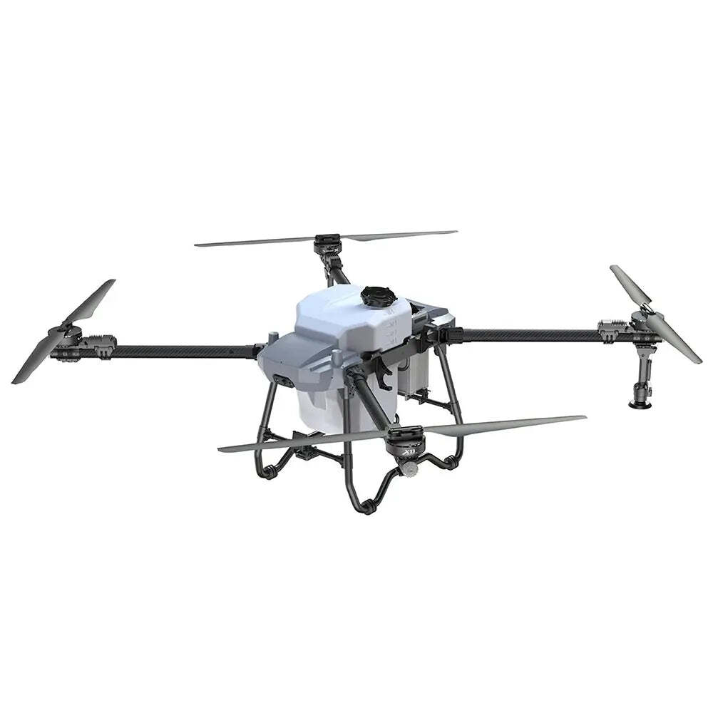
 UA50 catalog reference for the standard configuration. Confirm item identities and quantities against the current quotation; the image is not a signed packing list.2. Draw the energy path before comparing power ratings
There are two different systems to understand: the energy carried by the aircraft and the equipment that replenishes it on the ground. The listed batteries supply the flight system. The optional gasoline generator is part of the ground-support offering. Its presence in the configuration menu does not establish an onboard combustion engine, fuel-cell system or in-flight battery-charging capability.
For procurement, draw a simple chain: site power source, approved charging interface, charging equipment, battery, aircraft. Identify the electrical boundary between each pair. A cable that physically fits does not establish the correct voltage, current limit, communication protocol, polarity, environmental protection or charging control. Likewise, a charger model containing a number does not prove its input rating. Obtain the actual electrical specification and the manufacturer's approved connection arrangement for the selected package.
This distinction also improves communication with the supplier. “We need a gas-powered drone” can describe the wrong requirement. “We need the UA50 with a documented off-grid battery-charging arrangement for this launch cadence” identifies the equipment and the system problem more precisely.
3. Separate launch cadence from flight durationDefine the launch interval as the time from one launch to the next. It contains more than airborne time. A battery change, inspection, refill, route adjustment and clearance for the next departure can all extend the interval. Some activities may overlap; others require the same person or piece of equipment and therefore cannot happen simultaneously.
Use a timestamped observation rather than a remembered average. Record launch, landing, battery removal, next battery installation and next launch. Also record when the removed battery becomes eligible for charging, when charging starts, when it ends and when the pack is released for service. These events reveal the difference between a battery that is electrically charged and one that is actually ready for the next dispatch under the applicable instructions.
For the worked example, assume an eight-minute airborne period followed by two minutes of ground turnaround. The planned launch interval is therefore ten minutes. Those values are hypothetical and do not describe a tested UA50 sortie. They simply establish a common clock for comparing battery demand with recovery. At that cadence, the system asks for a ready battery six times per hour. Whether a particular field operation can or should use that cadence is a separate question.
4. Track each battery as an item moving through a queueA removed battery passes through several states: awaiting inspection, cooling or otherwise becoming eligible for charge, waiting for a charging position, charging, and awaiting release. Use the requirements in the battery and charger instructions to define those states. Do not replace eligibility checks with a fixed timer merely because a fixed timer makes the spreadsheet easier.
In an initial model, let F be airborne time, L the launch interval, C the time between removal and charge eligibility, Q the charging queue, H the charging service time, and R the release time after charging. For a round-robin inventory of B batteries, a useful screening condition is:
B × L ≥ F + C + Q + H + RThe left side is the scheduled time until the same battery is needed again. The right side is its first airborne period plus its recovery sequence. This relationship assumes that battery removal occurs at the end of F and that the other timing definitions are applied consistently. It is a scheduling model, not a battery-safety rule. It also contains Q, which is determined by the charging system rather than by the battery inventory alone.
Consider C of six minutes, H of fourteen minutes and R of two minutes. With no queue, the battery launched at minute zero lands at minute eight, becomes charge-eligible at minute fourteen, finishes charging at minute twenty-eight and is released at minute thirty. Three batteries appear sufficient for a ten-minute launch interval because the first battery is scheduled to return at minute thirty. But that conclusion fails if it ignores what happens to the second battery.
5. Expose the bottleneck with an event timelineAssume there is one charging channel and retain the example above. Battery A launches at minute zero; battery B launches at minute ten. Battery B lands at minute eighteen and becomes eligible for charging at minute twenty-four. The charger is still occupied by A until minute twenty-eight. B therefore waits four minutes, charges until minute forty-two and is released at minute forty-four. A three-battery rotation would have asked B to launch again at minute forty. The schedule is already four minutes late.
Example only: one charging channel, launch interval 10 minutes
Battery First launch Charge eligible Charge start Ready again
A 0 14 14 30
B 10 24 28 44
C 20 34 42 58
The queue grows because each arriving battery requires fourteen minutes of charger service but a battery arrives every ten minutes. Adding a fourth battery may postpone the first missed launch. It does not remove the continuing four-minute deficit per arrival under these assumptions. Over a sufficiently long operating window, waiting inventory still accumulates.
A necessary capacity check for m independent charging channels is m multiplied by L being at least H. Another way to express the same idealized load is utilization equal to H divided by m times L. One channel in this example has a utilization of 1.4 and cannot sustain the assumed arrival rate. Two genuinely independent channels give an idealized utilization of 0.7. That creates capacity headroom, but it does not prove the full system works: both channels must have the required power, controls, thermal conditions and staffing.
Count effective charging channels rather than connector positions. A two-port device may share its available power, changing the service time when both ports are used. Measure that operating condition directly. Do not assume that connecting two batteries creates twice the replenishment capacity.
6. Use battery energy as a consistency checkThe current seller declaration identifies 18S 30Ah batteries and lists a battery voltage of 68.4V. Multiplying that listed voltage by capacity gives a reference voltage-capacity product of 2,052Wh, or 2.052kWh. This arithmetic is useful for checking units and the scale of the system. It is not a measurement of usable flight energy, a permitted discharge depth or a prediction of charging time.
For operational planning, meter the energy transferred across a clearly defined boundary. If the meter is at the charger input, its reading includes losses inside the charging equipment. If another reading is taken at a generator output, it may include a different set of losses and auxiliary loads. Label both measurements so that they are not silently treated as the same quantity.
Suppose a separate hypothetical trial measures 1.2kWh at the charger input to recover one battery through the team's approved operating window. Repeating that recovery six times per hour would require an average of 7.2kW at that measurement boundary before adding other loads or reserve capacity. The fourteen-minute service-time example would correspond to about 5.14kW average input while one such recovery is active. These are consequences of the assumed measurements, not ratings assigned to the U9000 charger.
Average energy demand and instantaneous power demand answer different questions. A source can have enough total energy for the day but fail when simultaneous charging loads begin. A source can also support a short high-power interval while consuming fuel or stored energy too quickly for the intended work window. Evaluate both, and keep all quantities tied to the same measurement boundary.
7. Read the optional generator specification by output typeThe current seller declaration for the optional 18S-9000W generator distinguishes a maximum DC output of 9000W from a maximum AC output of 1000W. Those are different outputs. The larger number must not be treated as the rating of an ordinary AC outlet. A proposal to use this option should include a documented diagram showing which approved output feeds which charging equipment and through which specified interface.
The U9000 charger included in the declared standard package should be identified separately from the optional generator. Do not assume that matching numbers in their names establish an approved connection, simultaneous output capacity or the charging service time used in the schedule. Request the permitted topology, input/output limits, protective arrangements and any configuration-specific accessories from the supplier.
The catalog also lists a short battery charge-time reference. It is excluded from the worked schedule here because its complete test conditions and its relationship to the selected ground-power topology have not been established. A useful quotation should state the starting and ending charge levels, battery temperature conditions, charging mode, power-source arrangement and whether any other battery was charging simultaneously. A duration without those conditions is inadequate for designing a rotation.
Generator selection must also consider the intended site. The current declaration is not a regional electrical, emissions or fuel-safety certificate. Have the qualified local team confirm the applicable installation and operating requirements. The procurement document should specify the arrangement that will be supplied rather than leaving those dependencies to be discovered after delivery.
8. Measure variation before choosing extra-battery quantityAn average recovery time conceals the cases that interrupt dispatch. Record individual cycles and retain the sequence. Cooling delays may increase later in a warm operating period; a charger may behave differently when multiple positions are occupied; a technician may need extra time to investigate a warning. The sequence helps distinguish a persistent capacity deficit from an occasional disturbance.
Build the inventory decision around an agreed service target. For example, the buyer might require that a specified proportion of planned launches have an eligible, released battery available during a defined observation window. The team must choose that target and the representative test conditions. Do not invent a percentage and present it as an aircraft capability.
Evaluate at least a normal case and a disruption case. In the disruption case, remove one battery from service, delay one charging channel or extend one eligibility interval, then recalculate the dispatch sequence. An extra battery may be valuable if it absorbs that finite disturbance. If the queue grows continuously even in the normal case, address source or charging capacity before buying inventory to hide it.
9. Turn the model into a configuration-specific RFQSend the supplier the intended operating clock and ask for an itemized response. Include the planned launch interval, expected flight and ground-turnaround observations, site power availability, environmental range, number of aircraft sharing the support equipment, and the period for which the system must sustain work. State which numbers are measured and which remain assumptions.
Request the total battery quantity and the distinction between standard and additional batteries. Identify the exact battery revision, the charger model and effective channel count, permitted simultaneous use, source requirements, cables and documented interfaces. If the optional generator is selected, request separate DC and AC output information and a drawing of the approved charging arrangement. Ask whether the proposal changes the equipment schedule or only adds an option to the existing schedule.
The quotation should also define what evidence will demonstrate that the proposed system meets the agreed work cycle. A reasonable commissioning record contains time-stamped battery events, charging-channel occupancy, energy readings at defined boundaries, environmental observations, alerts and maintenance actions. It should identify the aircraft, batteries, charger and power source used. A different configuration should not inherit the result without review.
Avoid turning this test into a promise about hectares per hour. Accepted application area depends on a separate set of agronomic, calibration, route and operating conditions. Energy per accepted hectare can be a useful later metric, but only when the application result has been independently accepted and the same observation window is used. GPS coverage alone does not establish application quality.
10. Make the purchase decision from the limiting resourceThe right extra-battery choice depends on the bottleneck. If batteries are routinely ready but ground turnaround is slow, more battery inventory may contribute little. If one short recovery delay causes an otherwise stable system to miss a launch, an additional eligible pack may provide useful resilience. If charging service exceeds arrivals, source and charger capacity need attention. If the approved electrical arrangement remains unclear, the quotation is not yet complete enough for an energy-system decision.
For the UA50, the immediate advantage of a precise configuration review is that the current menu separates extra batteries, the 80L spreader and the gasoline generator. The buyer can therefore ask distinct questions about inventory, application hardware and ground power instead of treating them as one undifferentiated upgrade. Use that separation to obtain a proposal whose contents and dependencies are visible.
The strongest commissioning outcome is a repeatable record: the correct equipment is present, the charging arrangement is documented, each battery's state is known, and the observed recovery process supports the agreed launch schedule with the chosen reserve. That record is more useful than a package photograph, an isolated maximum-power number or a single fast charging demonstration.
Product reference and next stepReview the
current UA50 configurations and product declaration. For a focused quotation, provide the operating country, intended work cycle, total aircraft count, site electrical supply, desired extra-battery quantity and whether off-grid charging or the optional spreader is required. Ask UNITED UAV to confirm the exact standard package, selected options and approved charging topology in writing.
Commercial disclosure: Published by UNITED UAV Official. UNITED UAV sells the UA50 discussed in this article. Product specifications above are attributed to the current seller declaration; the worked timing and energy examples are analytical illustrations and do not represent field-test results, manufacturer certification or promised output.

 IRC Chat
 Like Us


