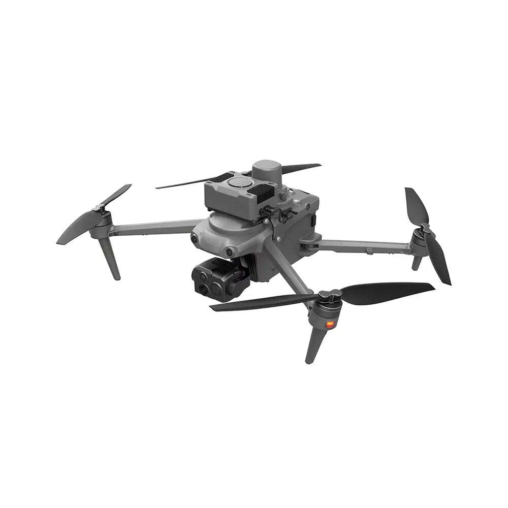
 Roof Inspection with the UIS220: A Field-to-Report Method for Visual and Thermal Evidence
A professional roof survey is not a collection of attractive aerial photographs. It is a controlled attempt to answer specific maintenance questions with traceable evidence. Where is the membrane discontinuity? Which flashing detail deserves a closer physical inspection? Has a previously mapped anomaly changed? Can another inspector locate the same feature without guessing from a cropped image? The aircraft is useful only if the flight plan, payload, environmental record, image quality, interpretation rules and final report all serve those questions.
The
UNITED UAV UIS220 product listing identifies the aircraft as an industrial inspection platform and offers several selectable configurations. Its default option is described as "Just one drone without any payload." Accordingly, this method never assumes that a thermal camera, telephoto camera, RTK module, cellular module or docking station is included in a particular purchase. Confirm the exact payload and deliverable files before committing to an inspection specification. The practices below are a field method, not a claim that any aircraft can diagnose a roof by itself.
1. Define the decision before defining the flightStart with the asset, not the drone. Obtain a roof plan or create a simple zone map showing the roof boundary, elevations, access points, drains, parapets, plant, skylights, solar arrays and known repairs. Record the roof-system type and the owner's question. A post-storm screen for visibly displaced components needs different imagery from a condition baseline, a leak investigation or a survey intended to identify candidate wet-insulation areas. For each question, write an observable acceptance condition. "Document every drain and adjacent membrane from at least two useful views" is auditable; "inspect the entire roof thoroughly" is not.
Separate what the imagery can establish from what it can only suggest. Visible photographs can document tears, punctures, open laps, displaced flashing, ponding residue and physical debris when resolution and viewing angle are adequate. They cannot prove the hidden extent of water intrusion. Thermal imagery maps apparent surface-temperature patterns under particular environmental conditions; a warm or cool area is not, by itself, proof of moisture, a leak path or failed insulation. A roof professional should decide which exceptions require a close-up, a moisture meter, a core sample or another accepted verification method. That distinction prevents a colored thermal map from being mislabeled as a repair specification.
2. Treat aircraft configuration as an inspection controlThe UIS220 page lists wide-angle, telephoto and thermal imaging capabilities in its product material, alongside optional RTK, 5G and docking-related configurations. The selectable variant, however, must be read literally: the base option says there is no payload. Request an itemized configuration with aircraft, gimbal, exact camera module, controller, batteries, charger, storage media, firmware versions and any licenses or software needed to export original images. Do not infer inclusion from a photograph of a fully equipped aircraft. Verify that the selected thermal module produces the required still images, radiometric data if temperature analysis is in scope, and metadata accessible to the intended review software.
Before the first client mission, capture a short test set over known roof details or a safe equivalent target. Examine unprocessed originals at full resolution. Check whether the wide image resolves seams and small fasteners at the planned standoff, whether the telephoto view remains sharp at the distance needed for safe clearance, and whether a thermal file preserves measurement settings rather than only a color palette. Record the serial numbers and installed payload identifiers in the job file. A specification-sheet pixel count does not replace this acceptance test, because focus, motion blur, compression, viewing geometry and target contrast determine the usable detail.
3. Build a roof-specific hazard mapThe takeoff area, roof edge and facade are parts of one operational volume. Mark potential aircraft hazards: rising exhaust, HVAC discharge, cranes, guy wires, antennas, overhead utilities, high parapets, glazing that can confuse visual sensing, narrow light wells and areas where GNSS reception may be poor. Also mark people and property at risk below the flight path. Establish a practical stand-off from the roof and obstacles for the actual aircraft, wind and camera combination; do not borrow an arbitrary distance from another site. If the needed image detail would require an unsafe approach, change lens, viewpoint or inspection method instead of eroding the clearance.
Conduct a preflight that includes propellers, arm locks, battery condition, payload attachment, gimbal movement, storage space, navigation status, return behavior and controller-link quality. Define where the aircraft should go after a link loss or low-battery event, and check whether that route crosses a roof obstacle or occupied area. The product's published maximum flight time is a ceiling stated without conditions specific to this roof, not a usable roof-coverage promise. Reserve enough energy for repositioning, unexpected headwind and an unhurried landing. Confirm the local aviation, site-access, privacy and night-operation requirements applicable to the job; they vary by jurisdiction and cannot be inferred from a product page.
4. Design visual coverage in two layersUse a context pass to make the roof navigable to someone who was not present. A high-level nadir or near-nadir set can establish roof-zone boundaries, drainage direction, equipment locations and relationships between findings. Maintain deliberate overlap between adjacent frames so that a reviewer can follow one feature across images. If an orthomosaic or dimensional comparison is part of the deliverable, plan the overlap, camera geometry and control for that output rather than assuming every set of overlapping photographs will reconstruct reliably.
USGS guidance on UAS image calibration explains why acquisition geometry and ground control affect accuracy; ground sample distance alone is not a positional-accuracy certificate.
Add a detail pass for failure-prone interfaces: penetrations, curbs, expansion joints, edge metal, parapet caps, scuppers, drains and previous patches. Capture each finding with three linked views: a wide locator image, a medium view that shows the surrounding assembly, and a close detail that can support a maintenance decision. A close crop without a locator can be impossible to place on a large commercial roof. Use oblique views to see raised laps or vertical flashing faces that a straight-down image hides. Where a telephoto payload is actually installed, prefer an optically sharp image at a safe standoff; digital enlargement cannot recreate detail that the sensor never captured.
Decide the smallest feature that matters before selecting altitude. A simple planning estimate is ground footprint divided by image pixels along the same axis, but the roof is not a flat calibration chart. Oblique views stretch pixel footprints away from image center, and high-contrast seams may be visible at a different scale from low-contrast punctures. Make a short pilot pass, inspect originals at 100 percent, and adjust height, angle or capture interval. Do not promise that a quoted megapixel number will detect every crack. For repeat surveys, keep the same zone boundaries and document any change in height, lens or viewing angle so apparent differences are not mistaken for roof deterioration.
5. Use thermal imaging as a hypothesis testThe relevant physical signal is heat flow, not a color. After solar heating, different roof areas may cool at different rates; construction layers, retained moisture, shading, surface contamination and reflected radiation all influence the pattern.
ASTM C1153-23 addresses night-time infrared location of wet insulation for a defined class of roofs with insulation above the deck in contact with the waterproofing. It covers ground and aerial imaging, environmental conditions and verification, but it does not identify the moisture entry point or establish that a roof is watertight. Do not present a general daytime temperature survey as compliance with that specific practice.
For a thermal assignment, log recent rain, cloud cover, solar exposure, wind, ambient temperature and the inspection time. Note shadows from plant and parapets, wet surface water, reflective metal and differing roof materials. Compare like areas under similar conditions. A hot mechanical unit can reflect in a low-emissivity surface; a dark patch in a palette can simply be a scale choice.
FLIR's thermography measurement guidance identifies emissivity, reflected apparent temperature, distance and atmospheric factors as inputs to temperature measurement. Record the settings actually used, and preserve the original radiometric file if quantitative claims are made.
Pair every thermal exception with a visible locator image. Outline the candidate area, note its relation to drains or seams, and assign a confidence level based on repeatability and competing explanations. If the pattern disappears after changing viewing angle, investigate reflection. If it follows a structural bay or a material boundary, investigate construction before calling it moisture. Ask a qualified roof specialist to select a small number of verification points; invasive confirmation may be necessary for a wet-insulation conclusion. A thermal camera cannot see through an opaque roof membrane, and temperature contrast cannot by itself determine a leak's source.
6. Keep geometry and positioning honestRTK can improve the recorded camera position when an appropriate module, correction source and fixed solution are present. It does not turn every pixel into a survey-grade coordinate, and it does not correct blurred imagery, an inaccurate camera model or a poorly surveyed roof plan. If the deliverable requires measured areas or repeatable coordinates, define the required accuracy with the client and use suitable control and independent check points. Record coordinate reference system, vertical datum where relevant, control method, checkpoints, processing software and residuals. If those elements are absent, describe locations as approximate roof-zone references, not certified measurements.
The
USGS calibration guidance distinguishes pixel resolution from geometric accuracy and discusses the roles of tie points and ground control. Apply that lesson to commercial roofs: use repeatable image geometry and well-distributed control where measurement is requested. For simple defect documentation, an annotated roof plan and photo IDs may be more defensible than a superficially precise coordinate. The purpose of location data is to help a crew find the defect, not to create false precision. Provide enough context that a technician can reach the correct penetration or flashing segment without relying on the inspector's memory.
7. Run quality assurance while the aircraft is still on siteDo not leave the site with only a green flight-complete indicator. Review at least one original image from each roof zone and each imaging mode before packing up. Check focus at the corners, exposure on white and dark surfaces, motion blur near edges, shadow loss under equipment, thermal saturation, missing geotags, timestamp drift and whether the final row of images actually covers the roof boundary. Re-fly a failed zone while weather and access are still available. If a camera pauses recording during a battery change, log the gap explicitly.
Use a compact coverage matrix with rows for zones and columns for context, seams, penetrations, drains, edges and thermal frames where applicable. Mark each cell complete, blocked or not applicable. "Blocked" should carry a reason, such as a safety standoff, tenant privacy restriction or equipment shadow. A client can then distinguish an uninspected area from an area with no observed defect. This is more valuable than a large image count: 900 near-duplicate frames can still omit one critical scupper.
8. Classify observations without overstating themWrite an observation in three parts: what the image shows, why it matters, and what should verify it. For example: "The visible frame shows a lifted edge at the north side of drain D-04; water-flow direction and the nearby ponding stain make the detail a priority for close inspection; the aerial image alone does not establish a leak." This wording is actionable without turning an image into a warranty finding. Distinguish observed surface condition from inferred mechanism and from recommended next step.
Use consistent severity labels tied to response, not adjectives. An urgent field check might mean a visibly open penetration above sensitive equipment. A scheduled check might mean a small seam irregularity without an observed opening. A monitor item might mean a repeatable thermal contrast with no visible defect and no confirmatory test. Define the labels in the report so two reviewers do not apply different thresholds. Also record negative evidence: a drain was visible and clear in the captured frames, or a previously photographed patch appears unchanged under comparable lighting. Negative evidence is only meaningful where coverage and image quality are documented.
9. Preserve the evidence chainKeep original files read-only after transfer. Generate working copies for crops, annotations, orthomosaics and color adjustments, and retain a manifest that maps each derivative to its source. Store capture time, camera/payload identifier, flight or battery number, roof zone, weather notes and operator. If a thermal palette is adjusted, preserve the original temperature data and record the display range used in the report; palette changes can make the same data look more or less dramatic. If software aligns visible and thermal images, verify the alignment around roof edges and vertical objects rather than assuming the overlay is exact.
A simple file convention helps: site ID, visit date, zone, pass, sensor and frame number. The report should refer to stable IDs, not transient filenames assigned by a messaging app. Keep client-sensitive images under an agreed access policy; roofs may reveal security equipment, access routes or occupants. If the inspection is repeated after repair, preserve the baseline, repair record and follow-up separately. Do not silently replace an earlier image with a corrected or sharpened version. An auditable chain lets a second reviewer reconstruct how a conclusion was reached.
10. Deliver a decision-ready reportThe first page should state scope, date, weather, roof type if known, equipment configuration, zones covered, zones not covered and the limits of the method. Then provide a roof map with numbered findings. Each finding needs a locator, visible detail, thermal companion if used, concise observation, confidence, reason for uncertainty and recommended field verification. Include an exception table sorted by response priority, not by the order in which frames were captured. If a measured area is supplied, disclose the method and accuracy basis. A color thermal picture without its scale, capture time and paired visible image should not be presented as a diagnostic result.
The final section should answer the commissioning question directly. If the objective was a post-storm visual screen, say which components were checked and which could not be seen. If the objective was candidate wet-insulation mapping, present candidates and verification status without claiming a confirmed moisture footprint before testing. If the objective was a repair closeout, compare equivalent pre- and post-work views and list any differences in acquisition conditions. Attach the image index and raw-data handover instructions. The report should enable an owner to authorize the next physical inspection or repair step with a clear understanding of what the UAV did and did not establish.
11. An example acceptance gate for a commercial roofConsider a flat-roof site divided into five zones, with two equipment clusters and several drains. Before flight, the owner provides a roof plan and asks for a visual condition baseline plus a thermal screen of candidate insulation anomalies. The operator first checks whether the selected UIS220 configuration actually includes both visible and thermal payloads and whether the thermal export is suitable for the intended analysis. A daytime visual mission maps drains, curbs and perimeter details; a separate thermal mission is scheduled only if roof construction, weather and operating permissions make the method appropriate. These are different capture conditions, not one automatic "multi-sensor" flight.
The acceptance gate is explicit: every zone has a context image; every drain and penetration has a useful medium and detail image; every thermal exception has a visible locator and environmental record; original files and a coverage matrix are delivered; and each inaccessible area is labeled. A reviewer checks image sharpness and source-file links before accepting the report. One verified anomaly may lead to targeted physical testing, while a visually intact area is recorded only as "no visible exception in the acquired views." This scenario avoids inventing a universal flight altitude, a promised defect-detection size or a moisture diagnosis from the image alone.
12. Where the UIS220 fits, and what to verify before purchaseThe UIS220 is relevant to this workflow because the official listing positions it for inspection and provides options for wide, telephoto and thermal sensing, with additional modules listed separately. That makes configuration control central to procurement. Ask for the exact camera model and raw-file examples; the installed lens and sensor determine whether the required roof detail is achievable from a safe standoff. Ask how batteries, controller and carrying case are packaged for the chosen variant. Verify whether any RTK or cellular function is included or optional, and test data export and repeatability before promising a client-specific deliverable. Published maximum flight time and link range should remain planning references, not commitments for a cluttered urban roof.
UNITED UAV supplies a broader range of UAV systems and components; this note concerns one roof-inspection application, not the full scope of the brand. A good aircraft selection follows the inspection question, risk envelope and required evidence. If the job requires a thermal moisture survey, obtain the appropriate payload and qualified interpretation. If it requires only visible close-up documentation, a simpler configuration may be enough. The defensible outcome is a traceable roof decision, not a persuasive collection of drone footage.
Method references and product configurationCommercial disclosure: This technical article is published by UNITED UAV Official. The linked UIS220 product is sold through the UNITED UAV store. The operational method and cited standards are not a claim that a particular purchase includes every optional payload, satisfies a jurisdiction's flight rules, or replaces a qualified roof assessment.

 IRC Chat
 Like Us

