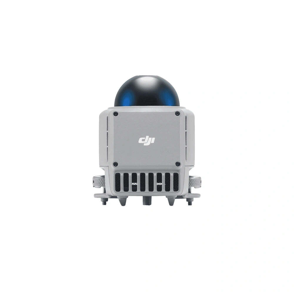
 Engineering the DJI Matrice 4 Obstacle Sensing Module into an operational safety case
The DJI Matrice 4 Obstacle Sensing Module is easy to describe as an accessory and much harder to integrate responsibly. Model LR-01 combines a rotating LiDAR with millimeter-wave radar for compatible Matrice 4 and Matrice 4D aircraft. That combination can expand the sensing information available to the flight system, especially around thin conductors and low-light operations. It does not turn an aircraft into an autonomous collision-proof machine. The useful engineering question is therefore not simply, “Can we mount it?” It is, “What hazards does this module help control, under which conditions, and how will the operator prove that it is installed, configured and performing as expected?”
This guide treats the module as one layer in a larger operational safety case. It covers selection, mechanical integration, activation, acceptance testing, mission planning, maintenance and evidence. The objective is to help inspection teams, public-safety units, infrastructure operators and dock-program managers make a defensible deployment decision instead of treating a sensor specification as a substitute for risk analysis.
1. Establish the exact equipment baselineStart with the product identity. The selected item is the DJI Matrice 4D / Matrice 4 Series Obstacle Sensing Module, model LR-01. DJI lists a mass of 235 g and dimensions of 103.3 × 64 × 85.8 mm. The published operating-temperature range is -20 °C to 50 °C. DJI describes the sensing architecture as a rotating LiDAR plus millimeter-wave radar. The rotating LiDAR field of view is listed as 58 degrees vertically and 360 degrees horizontally; the radar field of view is 90 degrees vertically and 90 degrees horizontally. DJI lists a maximum detection distance of 100 m, but that headline value must not be confused with a universal usable range for every target.
The official specification also states an effective sensing-speed condition of no more than 15 m/s for a 12 mm steel-core aluminum stranded wire. That is a tightly defined test condition, not a promise that every 12 mm object will be detected at every aspect, distance, weather condition or closure rate. Conductor material, background, orientation, atmospheric attenuation, platform attitude, relative motion and firmware behavior all influence the operational result. A team should preserve the wording and conditions of the source specification in its acceptance record rather than reducing it to “detects wires.”
Compatibility is similarly specific. The store listing identifies DJI Matrice 4D Series and DJI Matrice 4 Series aircraft, with current firmware required. The kit includes the module, H2.5 and H1.5 hex keys, a Matrice 4 adapter bracket and twelve reflective stickers intended for DJI Dock use. The bracket matters because the physical installation differs between aircraft families. Confirm the exact aircraft model, module part number, included bracket and current DJI documentation before issuing the equipment to a crew. A familiar name is not enough for configuration control.
2. Understand what sensor fusion changes—and what it does notLiDAR and millimeter-wave radar observe the environment through different physical mechanisms. A rotating LiDAR measures optical time of flight and can build angularly dense range observations across its scan. Radar uses reflected radio energy and may continue to produce useful returns where visible-light imaging is weak. Combining them can broaden the set of conditions in which an obstacle is represented, but the sensors do not erase each other’s blind spots or uncertainty.
Thin conductors are a useful example. Their apparent cross-section changes sharply with view angle. A wire crossing the flight path may present a different return from one aligned nearly along the viewing direction. Background clutter, supporting hardware, vegetation movement and precipitation can complicate interpretation. A sensing system may first acquire a conductor at one distance, lose it briefly, then reacquire it as geometry changes. Operators should plan for this variability and avoid turning the first alert distance observed in a test into a fixed operational constant.
The module also works inside an aircraft system that already has native vision and ranging sensors, flight-control logic, configured obstacle-avoidance behavior and operator inputs. The LR-01 is therefore not a standalone safety device. Its output is interpreted by aircraft firmware and presented through DJI Pilot 2 or FlightHub 2 workflows. An alert, stop or bypass response depends on software state, mode, speed, geometry and configuration. The pilot or remote-operations supervisor remains responsible for understanding what response is expected and what escape action remains available.
3. Convert the specification into a purchase decisionA sound procurement decision begins with the hazard register, not the catalog. Write down the obstacles and environments that create unacceptable exposure in the intended missions. Examples may include distribution conductors, shield wires, communications lines, crane cables, suspended structures, narrow corridors, nighttime substations or low-contrast industrial surfaces. For each hazard, record the likely diameter, material, orientation, background, approach direction, minimum planned stand-off and environmental envelope.
Next, ask whether the module addresses a meaningful part of that exposure. If missions are conducted mainly in open terrain at conservative stand-off distances, improved thin-object sensing may provide limited incremental value. If the aircraft repeatedly traverses complex utility corridors or supports dock-based inspection near conductors, the added sensing layer may justify its mass, cost, commissioning effort and maintenance burden. The answer should be tied to actual routes and incident data, not to a generic desire for “more safety.”
Account for system effects. Adding 235 g changes the aircraft configuration and may affect endurance, acceleration, braking margin and wind response. Use the applicable aircraft manual and in-app estimates to assess flight time; do not subtract a guessed percentage from the nominal endurance. Check whether other payloads or accessories compete for mounting space, interfaces or permitted combinations. Review transport cases, spares, weather protection, inspection tools, firmware-management procedures and crew training. The purchase price is only one part of the deployment cost.
4. Use a controlled installation processInstallation should be performed against the current DJI user manual and recorded as a configuration change. Power the aircraft off before attaching or removing the module. This protects the interface and avoids asking the aircraft to enumerate hardware during connection. Inspect the connector, sealing surfaces, module body, bracket and fasteners under good light. Reject damaged contacts, contamination, cracked housings, distorted brackets or fasteners that cannot achieve the prescribed fit.
Use the correct bracket for the aircraft family and the supplied tools where directed. Seat the module without forcing the connector. Tighten the mounting hardware in the sequence and manner described by DJI; “hand tight” is not a transferable torque specification unless the manual defines it that way. Confirm that the module cannot rock, that cables or covers are not pinched, and that no part obstructs other sensors. When the system is used with a dock, apply and manage the supplied reflective stickers exactly as the dock documentation requires rather than treating them as decorative labels.
Before first power-up, photograph the installation and record aircraft serial number, module serial number if exposed, bracket identity, installer, date and firmware baseline. This creates traceability if an intermittent issue appears later. It also prevents a module that passed acceptance on one aircraft from silently moving to another without a configuration review.
5. Activate and verify the digital configurationDJI documents two activation paths. For dock use, the aircraft should be powered and linked with the dock; the DJI Enterprise app is installed on a compatible Android phone, the phone is connected to the USB-C port of the dock electrical cabinet, and the on-screen activation workflow is completed. For operation with a remote controller, power the controller and aircraft, open DJI Pilot 2 and complete the activation prompt. Follow the current manual and local account-management policy because interface details can change with software revisions.
After activation, update the relevant devices to a mutually supported firmware baseline. “Latest” should be captured as explicit version numbers in the maintenance log. For a docked system, confirm the module icon is present in the FlightHub 2 device panel. For a controller-based system, confirm LR-01 appears on the DJI Pilot 2 home page. Absence of warnings is necessary but insufficient: also verify that the accessory identity persists through a controlled restart and that status remains healthy after the aircraft reaches operating temperature.
Do not perform firmware changes immediately before a critical mission. Treat updates as maintenance events: read release notes, stage the update, re-run acceptance checks and retain a rollback or grounding decision if behavior changes. In a multi-aircraft fleet, configuration consistency matters. A route validated on one firmware-and-module combination should not automatically be assigned to an aircraft with a different baseline.
6. Build an acceptance test that measures behaviorAn acceptance test should establish whether the installed system behaves consistently enough for the intended concept of operations. It is not an attempt to recreate DJI’s laboratory qualification. Use a controlled site, an approved test plan, competent personnel, a visual observer where required, conservative heights and speeds, and a readily accessible manual escape path. Never improvise tests around live energized conductors, traffic or uninvolved people.
Begin with static checks. Confirm the module identity, attachment, clean sensor windows, app status, time synchronization and log storage. Capture screenshots of status pages. With the aircraft restrained only as the manufacturer permits, check for unexpected warnings during startup. Then perform a low-risk hover in a clear test area to observe vibration, attitude stability, telemetry and any abnormal acoustic or thermal signs.
Progress to representative targets in stages. Use a visible, non-energized target whose location and dimensions are known. Test several approach angles, backgrounds and lighting conditions at speeds well below the published upper condition. Record first indication distance, aircraft response, operator response and closest approach. Repeat each condition enough times to expose variability; a single successful pass demonstrates little. Add a negative control in open space to check for nuisance behavior. If thin-object performance is essential, commission a test fixture designed and supervised by a qualified safety team rather than suspending ad hoc wire in an active flight area.
Define acceptance thresholds before testing. Examples include: module recognized on every cold start; no connection warnings during a specified observation period; alerts presented in the expected interface; repeatable response within a conservatively defined corridor; no unexplained false response in the negative control; and complete logs for every run. If a threshold fails, ground that configuration, preserve logs and diagnose the cause. Do not repeatedly fly until one pass happens to succeed.
7. Design the mission around residual riskEven after acceptance, route design should assume that an obstacle can be missed or acquired too late for the desired maneuver. Maintain stand-off based on aircraft dynamics, navigation uncertainty, wind, latency, target geometry and the consequences of a failed detection. The module supports risk control; it does not replace separation.
Speed deserves explicit treatment. DJI’s published 15 m/s condition refers to a specified 12 mm conductor. An operational speed limit should usually be lower and should reflect the tested geometry, stopping or bypass distance, remote-link latency and local procedure. Slow down before entering a conductor-rich segment rather than waiting for an alert. Avoid aggressive lateral motion that reduces time available for both the control system and the pilot to respond. Establish an abort point before the narrowest part of the route.
Weather remains part of the hazard assessment. DJI notes that clouds, fog, rain and snow can affect obstacle avoidance and bypassing. Contamination, condensation, glare, strong electromagnetic environments and moving objects also deserve consideration. The official notes state that the aircraft cannot actively avoid fast-moving objects because of safety-system limitations. A vehicle, swinging cable, moving crane component or another aircraft therefore requires procedural separation and active monitoring, not reliance on the module.
The remote crew should know what it will do when sensing information conflicts with the planned route. Define who can pause or abort the mission, how an alert is communicated, what telemetry is monitored, and how the aircraft is recovered if automatic behavior places it in a poor position. For dock operations, set exception-handling rules: a repeated obstacle event should trigger review, not an endless series of automatic retries.
8. Treat IP55 and temperature figures correctlyDJI lists IP55 for the module and specifies -20 °C to 50 °C operation. Those values are environmental design inputs, not permission to ignore installation state or weather procedures. The store listing notes that IP55 applies when the module is used with the Matrice 4D Series. A complete ingress-protection claim depends on the specified combination, proper fit, intact seals and correct installation. A Matrice 4 Series setup should be evaluated against its own documentation rather than inheriting the 4D statement.
Temperature affects more than whether electronics power on. It can influence batteries, condensation, icing, material stiffness and the time required for a stable system state. Moving equipment between cold and warm humid spaces can produce moisture on optical surfaces. Build acclimation and inspection time into dispatch procedures. If sensor surfaces become wet, dirty, iced or damaged, ground the aircraft until they can be restored under the approved maintenance process.
9. Maintain the sensing chain, not just the enclosurePreflight inspection should include cleanliness, damage, attachment, status recognition and firmware compatibility. Use only cleaning methods approved for the sensor surfaces; abrasive wiping can convert a minor contaminant into permanent optical damage. Check the bracket and fasteners after transport, a hard landing, unexpected vibration or contact with vegetation. Compare the module’s orientation with baseline photographs if displacement is suspected.
Periodic functional checks should be based on usage and consequence, not only calendar time. A dock aircraft exposed continuously to dust, precipitation and temperature cycling may need a different inspection interval from a controller-operated aircraft stored indoors. Trend connection warnings, nuisance detections, missed detections observed during controlled checks and any changes after firmware updates. Serial-level records make it possible to distinguish an aircraft issue from a module issue.
Define removal-from-service criteria in advance. Cracked housing, compromised seals, damaged connector contacts, persistent recognition failure, abnormal rotation noise, repeatable test failure or an unexplained change in detection behavior should trigger grounding and technical review. Field repair beyond the manufacturer’s authorized scope can introduce hidden alignment or sealing problems. Preserve logs and contact the appropriate service channel.
10. Create evidence that survives handoverProfessional operations need evidence that another person can audit. The configuration record should identify the aircraft, module, bracket, firmware, apps and dock or controller involved. The acceptance package should contain the approved test plan, site conditions, target description, flight logs, screenshots, results, deviations and sign-off. The operating procedure should state speed limits, route stand-off, weather exclusions, alert response and the conditions that force a return to manual review.
When the fleet or route changes, use change control. New firmware, a replacement module, a different aircraft, a modified route, a new obstacle type or a revised avoidance mode can invalidate part of the prior evidence. The response does not always need to be a complete requalification, but the responsible person should document why a limited regression test is adequate.
Metrics should measure the control, not create false precision. Useful measures include recognition success on startup, warning rate per mission hour, aborted missions caused by sensing anomalies, maintenance findings and repeated controlled-test performance. Avoid publishing a single “detection reliability” percentage unless the test population, target geometry and confidence bounds support it.
11. Procurement and commissioning checklist- Confirm the aircraft is a supported Matrice 4D or Matrice 4 Series model and identify whether dock or controller operation is intended.
- Confirm module model LR-01, included adapter bracket, hex keys and dock reflective stickers at receipt.
- Record the 235 g mass, 103.3 × 64 × 85.8 mm envelope and environmental limits in the aircraft configuration file.
- Review payload combination, endurance estimates, mounting interference and transport arrangements.
- Power off before installation; inspect connectors, sealing surfaces, bracket and fasteners.
- Activate through the documented dock or controller workflow and record explicit firmware versions.
- Verify the LR-01 identity in FlightHub 2 or DJI Pilot 2 and confirm status after restart.
- Run a controlled acceptance plan with known targets, multiple approach geometries and negative controls.
- Set conservative route speed, stand-off, weather exclusions, alert response and abort criteria.
- Create inspection intervals and grounding criteria tied to operating exposure and consequence.
- Retain logs, screenshots, photographs, deviations and approvals as part of the operational safety case.
Engineering conclusionThe LR-01 is most valuable when it is attached to a specific hazard-control argument. Its rotating LiDAR and millimeter-wave radar can add sensing diversity, and DJI publishes a meaningful thin-conductor test condition. Those facts justify evaluation for power inspection, industrial corridors and selected dock missions. They do not justify reducing separation, removing human oversight or skipping route analysis.
A mature deployment has five visible properties: the exact configuration is controlled; installation and activation are traceable; performance is checked against representative targets; operational limits remain more conservative than the edge of the published envelope; and anomalies cause review rather than normalization. If a team cannot maintain those properties, the module should remain an unclaimed accessory rather than a credited safety control.
Primary referencesCommercial disclosure: This technical article is published by UNITED UAV Official. UNITED UAV sells the product discussed here. Verify current specifications, regional availability, compatibility, firmware requirements and operating rules before purchase or deployment.
View the current DJI Matrice 4D / Matrice 4 Series Obstacle Sensing Module listing at UNITED UAV
 IRC Chat
 Like Us

